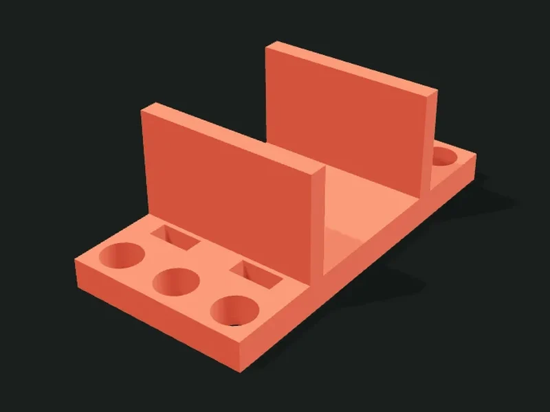
What it’s for
Parts to build robots compatible with LEGO® Technic™: straight, L and T beams, plates with a grid of holes, mounts for common motors (yellow TT, N20) and servos (SG90, MG996R), for the HC-SR04 ultrasonic sensor, plates for Arduino, ESP32 and Raspberry Pi, battery holder mounts, wheels, caster wheel (with a printed ball if you want), cross axles, angle connectors, bushes, a servo horn adapter, a coupler from the motor shaft to a cross axle, printed pins and a calibration piece. Everything uses the 8 mm pitch and 4.8 mm holes, so it combines with original parts. LEGO and Technic are trademarks of The LEGO Group, which doesn’t sponsor or endorse these parts.
Ideas
- Robot car with yellow TT motors, wheels and an Arduino board on a grid chassis.
- Robotic arm with SG90 or MG996R servos mounted on beams.
- Spare beams, plates and pins for school robotics kits.
- Connect a cheap motor to Technic gears and axles with the coupler.
Step by step
- First print the «Calibration piece» and try a LEGO pin and axle in each column.
- Enter the clearance of the column that fits best in «Hole clearance»: it applies to all parts.
- Choose the part: beam, plate, motor or servo mount, coupler or pins.
- Adjust the number of holes or the motor or servo model.
- Print lying down, as it comes on the bed: the holes come out vertical and round.
Tips
- For beams and pins use PETG or PLA with 3 perimeters: the holes hold up better to use.
- If a pin goes in too hard raise the clearance in 0.05 mm steps; if it’s loose, lower it.
- The motor and servo mounts have their holes on the same 8 mm grid: they attach with pins to any beam or plate.
- For the TT motor, the mount ends before the wheel so it turns freely; adjust the wheel diameter if you use a different one.
Presets
Parameters
Part
Which part to print and the hole clearance, which applies to all of them.
Which part to print: a beam, a grid plate, a motor or servo mount, the motor shaft coupler, pins or the calibration piece.
Thickness of the beam or plate: full (7.8 mm, like a normal LEGO beam) or thin (3.8 mm, like thin beams and plates).
How much bigger than the LEGO size the holes come out. Each printer is different: print the calibration piece and enter here the clearance of the hole that fits best. 0.15–0.25 mm is most common.
Beam
Shape, number and type of holes, and the beam’s thickness.
Beam shape: straight, L (two arms at 90°) or T (a bar with an arm in the middle).
Number of holes of the beam, or of the main bar if it’s L or T. The most common LEGO beams have 3, 5, 7, 9, 11, 13 and 15.
Number of holes of the other arm of the L or T beam, counting the corner or center hole.
Type of holes: all round for pins, cross only at the ends (like LEGO L beams) or all cross so an axle doesn’t turn.
Plate
Size of the plate in holes and where the holes go.
Number of holes of the plate lengthwise. Each hole is 8 mm: 11 holes give a plate of about 87 mm.
Number of holes of the plate widthwise.
Holes over the whole plate (more places to attach things) or only around the edge (sturdier plate, faster to print).
Motor
Motor model and its dimensions, and the wheel it carries.
Motor model: yellow TT (the one in robot cars), N20 (metal micro gear motor) or another with manual dimensions.
Width of the motor, measured along the shaft if it comes out the side. The mount adds 0.3 mm of play on each side.
Height of the motor resting on the mount. The cradle walls cover a bit more than half of this height.
Total length of the motor, from the back cover to the tip of the gearbox.
Where the shaft comes out: from the side (like the TT, the wheel sits next to the motor) or from the tip (like the N20, the wheel sits in front).
Distance from the motor’s tip to the center of the shaft when it comes out the side. On the TT it’s about 11 mm.
Diameter of the wheel on the shaft. The mount is shortened so the wheel turns without touching it; 0 leaves it full length.
Servo
Servo model and its dimensions.
Servo model: SG90 or MG90S (micro, the blue ones), MG996R or MG995 (standard, stronger) or another with manual dimensions.
Length of the servo body without the screw ears. It’s the length of the window it goes through.
Width of the servo body. It’s the width of the window it goes through.
Total length of the servo counting the screw ears. It sets the length of the plate.
Distance between the centers of the two holes in the servo’s ears.
Diameter of the hole for the servo’s self-tapping screws: a bit less than the screw, so it bites.
Electronics
Plate to mount an Arduino, an ESP32 or a Raspberry Pi on the robot.
Which board is mounted: Arduino Uno, 30-pin ESP32 DevKit, Raspberry Pi 4 or Raspberry Pi Zero. Those with holes are screwed down; the ESP32 snaps in between clips.
Height of the standoffs under the board. It leaves room for the solder joints and the pin tips sticking out; the ESP32 needs 10 mm or more because of its pins.
Battery holder
Mount for the battery box.
Which battery holder rests on it: the 2 or 4 AA one, the 2 × 18650 one, a 9 V battery or another with manual dimensions. Measure yours, because they vary by brand.
Width of the battery holder, from wall to wall of the cradle. 0.3 mm of play is added on each side.
Height of the battery holder resting on it. The cradle walls cover a bit more than half.
Length of the battery holder. The base covers it entirely and has two zip ties to hold it.
Wheel
Size of the wheel, the axle it takes and the tread.
Diameter of the wheel. For cars with a TT motor 56 to 66 mm is used; with N20, 30 to 45 mm.
Width of the wheel’s tread (the height of the printed part, which prints lying down).
Which axle goes in the center: a LEGO® Technic™ cross axle, the TT motor’s double-D shaft or the N20 motor’s D shaft.
Wheel tread: with a groove for an o-ring or a rubber band (the best grip), with a grip pattern (ideal in TPU) or smooth.
Cuts holes in the wheel between the center and the tread: it’s lighter and prints faster, without losing stiffness.
Caster
Size of the ball and height to the floor of the third support wheel.
Diameter of the caster wheel’s ball. A regular glass marble is 16 mm; steel bearing balls, 12.7 or 15.9 mm. It snaps in through the cup’s opening.
Whether you supply the ball (a glass or steel one, which rolls better) or the app prints it in two halves with a pin to glue them.
Distance from the face where the mount attaches to the floor. For the robot to sit level, it must equal the height of the wheels’ axle minus their radius, measured from the same face.
Axles
Length and number of cross axles to print.
Length of the axle in 8 mm modules, like LEGO axles: a 4-axle is 31.8 mm and an 8-axle, 63.8 mm.
How many axles of the same length to print together. They print lying down in an X shape so they don’t need support.
Connector
Shape of the angle connector and type of holes.
Connector shape: L (joins two beams at 90°), T (three beams) or cube (a hole in each of the three directions, to build 3D structures).
Round holes for pins or cross holes for axles. Sideways ones are teardrop-shaped, point up, to print without support.
Shape of sideways pin holes: teardrop (the 45° point on top lets them print cleanly without supports; the pin still fits) or round (perfect if you print with supports).
Bushings
Length and number of stops for cross axles.
Length of the bush: half a module (3.8 mm, the most common to stop a wheel) or a full module (7.8 mm, also works as a spacer).
How many bushes to print together. They’re small and easy to lose: print extra.
Servo horn
Dimensions of the horn that comes with the servo and length of the adapter’s beam.
Which servo horn is used: the single horn that comes with the SG90 or MG90S, the MG996R one, or another with manual dimensions.
Length of the servo horn from the center of the shaft to the center of the tip.
Diameter of the round central part of the horn, the one that fits on the servo’s shaft.
Width of the servo horn at the tip. The adapter’s recess follows the horn’s shape, from the center to the tip.
Thickness of the servo horn. The recess is made 0.3 mm deeper so the horn goes in fully.
Number of holes of the adapter’s beam, toward the side opposite the horn. The other parts of the robotic arm attach there.
Pins
How many pins to print at once.
How many pins to print together. Each pin joins two full-thickness beams; print extra because they get lost.
How the pins print: lying down with a half-millimeter flat base (strong and without supports), fully round lying down (with supports or brim, your choice) or standing (round and without supports, but weaker because the layers run across).